
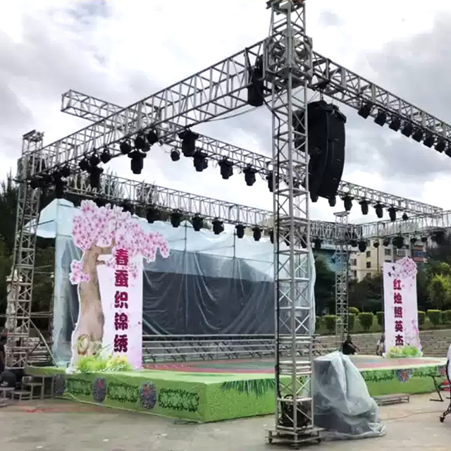
A touring LED wall may be assembled in the morning, operated for hours, dismantled at night, and transported to another venue before sunrise. Its aluminum structure must remain light enough for handling while keeping modules, locks, and adjoining cabinets accurately positioned. That balance is not achieved by choosing a strong alloy alone. Reliable LED stage frame manufacturing depends on how profile geometry, local machining, fastening, finishing, inspection, and spare-part compatibility are coordinated from the first CAD review. The following seven decisions help engineers and buyers focus on the interfaces that influence fast installation, stable screen alignment, repeated transport, and practical production—not merely the appearance of an individual frame.
Why a Stage Frame Must Be Designed Around Its Full Working Cycle
A stage frame is not a static enclosure. It passes through a repeated operating loop:
CAD review → extrusion → cutting → CNC machining → finishing → assembly → transport → installation → dismantling → reuse
Each stage affects the next. Machining may weaken a profile, finishing may alter a fit, and a handle may obstruct a lock. A dimension acceptable on one frame may create a visible step across a complete screen.
The manufacturing plan should therefore answer three questions early:
- Which features carry structural loads?
- Which interfaces establish visible cabinet alignment?
- Which parts must remain interchangeable after repeated production?
Decision 1 — Choose an Aluminum Profile Around Load Paths, Not Appearance Alone
The cross-section of an LED aluminum extrusion frame must support lifting, locking, module mounting, cable management, and transport protection. Adding metal everywhere increases handling weight; removing it everywhere can weaken corners and lock zones. Material should follow the actual load path.
During profile review, check:
- Where lifting and stacking forces enter the frame
- Which walls support locks, handles, and corner connections
- Whether screw ports have enough surrounding material
- Where later holes or slots will interrupt the section
- Which faces will become assembly or inspection datums
- Whether cable channels reduce stiffness near loaded joints
The profile should also provide realistic access for cutting, deburring, fastening, and inspection. An engineering guide to aluminum stage frame systems can help teams relate profile design to repeated assembly, alignment, and structural integration rather than evaluating the extrusion as an isolated rail.
Decision 2 — Separate Structural Features from Alignment Interfaces
Load-bearing members and module-positioning features do not perform the same job. If fasteners must carry load, locate components, and compensate for error simultaneously, tightening sequence can change the final position.
Define Which Features Locate and Which Features Clamp
Pins, machined shoulders, stops, and datum-related holes establish position. Screws and quick locks maintain contact. Clearance holes allow assembly without forcing components out of position. Each critical feature needs a clear function:
- Locate: establishes repeatable position
- Clamp: holds two located surfaces together
- Clear: permits installation or adjustment
- Protect: prevents impact or tool contact
If alignment fails, engineers can inspect the locating chain instead of increasing torque.
Build a Datum Chain Across the Complete Cabinet
An isolated hole position says little about the assembled display. The relevant relationship may extend across several components:
Frame datum → backplate seat → module locator → cabinet lock → adjoining frame
Inspection should follow this chain. A hole may meet its coordinate tolerance while the combined position of the backplate, lock seat, and adjoining cabinet still produces a step or gap. Datum planning should reflect how the screen is assembled, not simply which surface is easiest to measure.
Decision 3 — Use CNC Machining Where Accuracy Changes Assembly Performance
Not every surface on a modular LED stage frame needs tight control. Precision should be concentrated on interfaces that influence joining, replacement, module seating, and connector access. This reduces unnecessary machining while protecting function.
Frame feature
Suitable manufacturing control
Why it matters
Rail length and end condition
Controlled cutting and end inspection
Maintains the cabinet envelope
Lock seat
Datum-related CNC machining
Supports repeatable cabinet joining
Locating hole or slot
CNC position control
Preserves module and panel alignment
Connector opening
Position and edge control
Prevents interference and cable damage
Visible exterior rail
Defined finish and handling standard
Protects stage appearance
The drawing should identify critical relationships instead of applying tight tolerances everywhere. A functional callout around a lock seat provides more value than restrictive requirements on hidden, non-mating surfaces.
Decision 4 — Treat LED Frame Components as One Connected Assembly
A frame rail cannot be approved responsibly without considering its backplate, brackets, locks, connectors, handles, and modules. These parts compete for limited space and transfer forces through shared interfaces.
Coordinate Backplates, Locks, Brackets, and Cable Hardware
Assembly review should overlay every operating and service envelope. The backplate must support module position without obstructing locks. Connector bodies need insertion and release space. Cable restraints should prevent loose wiring from entering a joint, fan, or tool path. Handles must remain usable without loading a cosmetic edge.
Key interface checks include:
- Backplate flatness relative to the module-supporting plane
- Lock position relative to cabinet locators
- Connector clearance during cabinet joining
- Tool access after electronics are installed
- Clearance between transport guards and functional datums
Sourcing precision components for modular LED stage frames works best when the supplier receives the assembly model and mating-part information, not only separate drawings.
Decision 5 — Specify the Finish by Surface Function
Black anodizing or coating contributes to appearance and surface protection, but a single blanket instruction is rarely enough. Finishing may alter fits, cover electrical contact areas, enter threads, or change how a lock moves.
Divide the frame into functional surface classes:
- Primary cosmetic faces: visible during normal use and requiring controlled handling
- Secondary visible faces: visible only from certain angles or during assembly
- Hidden structural faces: evaluated mainly for protection and function
- Critical interfaces: locating, sliding, threaded, grounding, or electrical-contact areas
The drawing should identify masking, coating allowance, acceptable rack locations, and whether machining occurs before or after finishing. Packaging should then prevent finished rails from rubbing against hardware or one another during transport.
Decision 6 — Prove Interchangeability Before Releasing a Larger Batch
One carefully assembled prototype cannot demonstrate repeatability. It may contain selected parts, adjusted locks, or a mating pair that happens to fit. A rental LED display frame needs replacement components and cabinets from different batches to assemble without filing, shimming, or selective matching.
Cross-Match Parts Instead of Testing One Preferred Set
Validation should deliberately mix frames, backplates, locks, and representative spares. A useful sequence is:
Measure → assemble → cross-match → lock → inspect alignment → dismantle → repeat
Record every adjustment. If one lock works only with one frame, there is an interface-control problem even when both parts pass separate checks. Revision records should state which versions remain compatible for future replacement orders.
Decision 7 — Make Machining and Inspection Follow the Same Datums
Long aluminum profiles and thin backplates can move under clamping or after material removal. Fixture pressure, unsupported walls, machining sequence, and repeated setups may all shift the relationships that matter at assembly.
Planned aluminum CNC machining for critical frame interfaces should begin with the same datum logic used on the product drawing. Manufacturing and inspection teams should confirm that:
- Fixtures support thin walls without excessive distortion.
- Related holes and lock seats share a setup where practical.
- Cut ends are controlled relative to functional features.
- Inspection references match drawing datums.
- Final-fit checks account for the specified finish condition.
This approach connects machining results to cabinet performance. It also helps distinguish a genuine production variation from a measurement method that references the wrong surface.
What Buyers Should Include in an LED Stage Frame RFQ
The quality of a quotation depends on the information available during process planning. A useful RFQ package should contain:
- Complete cabinet and LED stage screen structure models
- Individual drawings with revision status
- Aluminum alloy and temper requirements
- Critical datums and mating interfaces
- Lock, locator, module, and connector information
- Cosmetic zones, finish, masking, and rack-point requirements
- Prototype, production, and expected spare-part quantities
- Cross-batch interchangeability expectations
- Assembly and functional inspection requirements
- Packaging and transport contact conditions
Buyers should identify which dimensions affect screen alignment and which are ordinary manufacturing features. This allows the supplier to propose appropriate extrusion, machining, fixturing, and inspection methods without guessing at functional priorities.
Reliable Stage Frames Are Manufactured as Systems, Not Separate Parts
Successful LED stage frame manufacturing connects profile geometry, load paths, datum strategy, CNC-machined interfaces, finishing, and inspection to the way a touring display is actually handled. Lightweight design should not remove support from corner joints or lock zones, while tight tolerances should not be scattered across features that do not influence fit. The strongest production plan concentrates control where cabinets join, modules locate, connectors operate, and replacement parts cross batch boundaries. By providing the complete assembly model, functional interfaces, quantities, finish expectations, and validation plan at the RFQ stage, buyers give the manufacturer the information needed to build a frame that performs beyond its first installation.